




Recent Posts
 Calibration Checks That Keep a Lipstick Break Force Tester Measurement-ReadySep 24, 2026
 Which ISO Test Conditions Matter for a Syringe Needle Puncture Tester?Sep 23, 2026
 How to choose the right load range for a bone screw insertion force testerSep 23, 2026
 How to select torque range for a bone screw torsion testerSep 22, 2026
 What does a bone screw torsion tester measure during implant testing?Sep 22, 2026

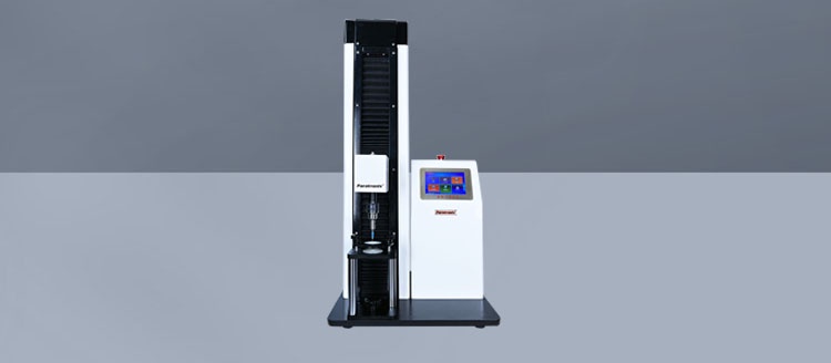
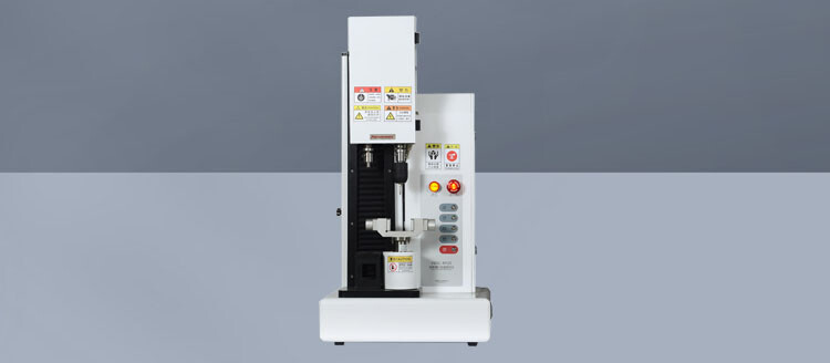
A lipstick break force tester is measurement-ready only when its force signal, mechanical loading path, fixture geometry, and result processing all agree. A passed load-cell check alone is not enough. If the fixture is tilted, the probe is contacting off-center, or the software is applying the wrong test method, the instrument can display a stable number that does not represent the lipstick’s actual resistance to breakage.
For maintenance work, the practical goal is not simply to “calibrate the tester.” It is to identify whether a reported change in break force comes from the sample, the test setup, or the instrument. A short, repeatable verification routine before scheduled calibration and after service work prevents many avoidable disputes between production, quality control, and equipment support.
Start with the force measurement chain
The load cell is the primary measuring element in a lipstick break force tester. It converts the applied load into the force value shown by the controller or software. Load cells can drift over time, but the more common service issue is a damaged or unstable measurement chain: loose connectors, strained cables, overloaded sensors, contaminated moving parts, or an incorrect zero point.
Begin with the instrument unloaded. Remove any lipstick sample, residue, adapter, or accidental contact between the probe and fixture. Allow the system to stabilize, then check whether the force display returns consistently to zero. A zero value that slowly moves, jumps intermittently, or changes when the cable is touched should be investigated before any calibration weights are applied.
Next, verify the force reading with traceable reference loads appropriate for the tester’s operating range. The point is not merely to check one load near the middle of the range. A tester can appear accurate at one point while showing increasing error at lower or higher loads. Use several checks spanning the force region normally used for lipstick testing, including the range where typical samples break.
During this check, observe more than the displayed value:
- Does the reading settle smoothly after a load is applied?
- Does it return close to zero after the load is removed?
- Does repeated loading at the same point produce consistent readings?
- Does the indication differ depending on whether the load is applied slowly or released slowly?
Repeatability problems often point to mechanical friction, connector issues, or sensor damage rather than a simple calibration offset. Adjusting the displayed value without finding the cause may make one reference point look correct while leaving daily tests unreliable.
Do not confuse calibration with a zero adjustment
Zero adjustment removes the unloaded signal offset. Calibration confirms the relationship between applied force and indicated force. These are related but different tasks.
A common mistake is to re-zero the tester whenever a result seems questionable. That may be appropriate when the fixture has been cleaned or changed and the unloaded force has shifted slightly. It is not a cure for inaccurate loading measurements. If a tester needs frequent zero adjustment, treat that as a diagnostic signal. Check for probe contact, debris under a fixture, preload from a cable, or instability in the sensor circuit.
After replacing a load cell, controller board, cable, probe assembly, or fixture-related component, verify both zero and force response before returning the equipment to use. The same applies after a suspected overload event, such as driving the crosshead into a rigid obstruction or using a fixture that exceeds the sensor’s intended loading condition.
Fixture alignment can change the apparent break force
Lipstick break testing is highly sensitive to how the force enters the product. The fixture must hold the lipstick in a repeatable position, and the loading probe must contact the intended point with the intended direction of travel. A sound load cell cannot correct a poor mechanical setup.
Inspect the sample holder for worn supports, damaged clamps, residue buildup, or loosened fasteners. Lipstick material can transfer to contact surfaces and gradually alter how far the bullet is exposed, how securely it is held, or whether it sits squarely in the holder. A holder that appears clean can still have a thin deposit that changes sample seating.
Check the probe face as well. It should be clean, undamaged, and installed firmly. A worn, rounded, chipped, or contaminated contact surface can change local stress at the loading point. That may shift the measured maximum force even when the sample itself has not changed.
Alignment should be checked with the crosshead moving slowly and without a test specimen in place. Confirm that the probe travels vertically relative to the fixture and reaches the expected contact position without side rubbing. If the probe approaches at an angle, the force can include bending, sliding, or frictional effects. Those effects commonly appear as inconsistent break-force curves or different results when the same sample is retested under nominally identical settings.
What to look for after fixture replacement
A replacement fixture does not automatically reproduce the old setup. Confirm the holder height, sample reference position, probe-to-sample location, and fastener tightness after installation. Even small changes in the exposed lipstick length or point of load application can materially affect the failure mode. The tester may be functioning correctly while the method no longer matches the established laboratory procedure.
Verify travel, speed, and the start-of-test position
Break force is a dynamic measurement. The crosshead speed, travel direction, initial clearance, and trigger condition influence how the tester reaches the sample. For this reason, maintenance checks should include motion as well as force.
Confirm that the crosshead moves smoothly throughout the travel used by the method. Listen for abnormal motor sounds, inspect lead screws or guide components according to the equipment design, and ensure there is no visible hesitation or backlash at the test position. Motion problems can create an irregular force trace or cause the probe to contact the lipstick differently from one test to the next.
The programmed test speed must also match the approved method. Increasing speed can alter the way a lipstick structure responds under load; reducing speed can introduce a different deformation pattern before failure. A calibration certificate for the load cell does not validate the selected speed. Review the stored method after controller resets, software updates, parameter changes, or operator complaints about unexpected results.
Pay close attention to the start position. If the probe begins too close to the sample, it may contact before the test begins properly. If it begins too far away, the procedure may add unnecessary travel and create opportunities for sample movement. A consistent pre-test clearance helps separate instrument behavior from variations in specimen placement.
Use the force curve as a maintenance diagnostic
The peak force is important, but it should not be the only information reviewed. When the system records force versus displacement or time, the curve can reveal problems that a single maximum value hides.
A curve does not prove the exact cause on its own. It does provide a practical direction for troubleshooting. Before changing calibration values, compare several curves from a controlled verification sequence. When the curve shape changes but the load cell check passes, focus first on mechanical condition and method execution.
Software settings deserve the same control as hardware
Incorrect method settings are one of the easiest ways to create credible-looking but unusable break-force data. Check that the correct test method is selected, especially when one instrument supports multiple product types or several lipstick formats.
The review should include force unit, test speed, travel limit, peak-force calculation, trigger logic, return behavior, and any break-detection setting used by the method. An incorrect force unit is obvious when noticed, but threshold and peak-detection settings can be more subtle. For example, a method that records a transient contact spike as the maximum force may overstate the result even though the specimen has not reached its intended failure condition.
Also confirm that the software receives the live signal from the correct channel and that saved results correspond to the active method. After computer replacement, software reinstallation, or controller communication repair, run a controlled test sequence before releasing the tester for routine work. This is especially important when historical data are used for batch comparison or trend analysis.
A practical maintenance schedule should follow risk, not habit
Daily readiness checks can remain simple: inspect the fixture and probe, confirm unloaded zero, verify free movement, and review the active method. These checks catch contamination, accidental contact, and setup errors before they enter the test record.
Periodic verification should be more deliberate. Apply reference loads across the working range, inspect mounting hardware and cable condition, verify alignment at the fixture, and review speed and displacement behavior. The interval should reflect use frequency, loading severity, internal quality procedures, and whether the tester is used for release decisions or investigative work.
After a repair, relocation, impact, overload, unexplained trend shift, or repeated failure of control samples, perform an expanded check rather than waiting for the next scheduled activity. A tester may still power on and move normally after such events, yet no longer produce comparable break-force results.
When results drift, isolate the source before recalibrating
When reported values begin moving away from the expected range, do not start by assuming the lipstick formulation has changed or that the load cell is defective. Use a controlled sequence: verify the reference load, inspect and clean the fixture, confirm the probe location and exposed sample length, review the active method, and compare the recorded curves.
If the force indication is incorrect under known reference loads, the measurement system needs corrective action. If the reference-load check passes but the lipstick results remain inconsistent, investigate alignment, sample preparation, conditioning, fixture geometry, and software parameters. This separation protects maintenance time and prevents unnecessary adjustments to a working sensor.
For laboratories supporting multiple packaging and material test methods, a documented verification routine also makes service handovers more reliable. Equipment providers such as Paratronix Instruments Co., Ltd., which develops packaging testing solutions for pharmaceutical packaging, plastic packaging materials, and high-barrier materials, can support a broader testing workflow. Still, the local service record should state what was checked, what reference was used, what changed, and whether the test method was reconfirmed.
A measurement-ready tester is not defined by a calibration label alone. It is defined by a verified force signal, clean and aligned tooling, controlled motion, validated software settings, and a maintenance record that makes abnormal results traceable. That combination gives quality teams a defensible basis for deciding whether a change belongs to the product or to the test system.
Leave A Reply
Search by Keywords